Protocol Management
Note
Images of GS1024E are for reference only; details may vary by model.
SNMP
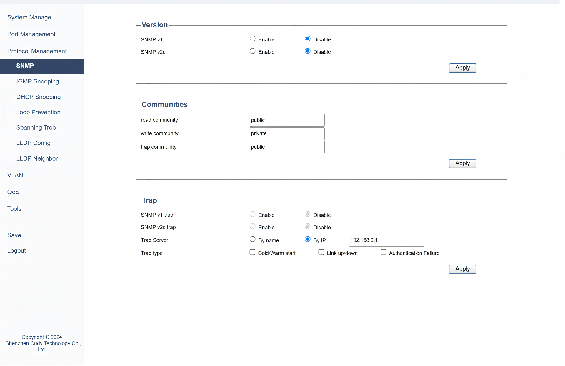
On the Protocol Management >> SNMP page, you can configure SNMP to manage and monitor network devices. It allows network administrators to collect information from and configure devices such as routers, switches, and servers. Please follow the steps:
1) Select a Version of SNMP. Click Apply.
- SNMP v1: Select to Enable or Disable it. It is the first version of the Simple Network Management Protocol (SNMP), providing basic functionality for network management but with limited security features.
- SNMP v2c: Select to Enable or Disable it. It is an enhanced version of SNMP that improves upon v1 with better bulk data retrieval and improved error handling, though it still lacks strong security mechanisms.
2) Configure the SNMP communities. Click Apply.
- Read community: Select Public or Private to allow read-only access, enabling monitoring but not configuration changes to managed devices.
- Write community: Select Public or Private to allow read-write access, allowing both monitoring and configuration changes to managed devices.
- Trap community: Select Public or Private to send SNMP trap messages, which are asynchronous notifications from agents to managers about significant events.
3) Configure the SNMP trap server and type. Click Apply.
- SNMP v1 trap: Synchronized with SNMP version selection.
- SNMP v2c trap: Synchronized with SNMP version selection.
- Trap Server: Select By name or By IP to specify the destination for trap messages, where the SNMP manager listens for traps.
- Trap type: Select a type of traps that indicate specific events: Cold/Warm start for a device reboot, Link up/down for a network link becoming active or inactive; Authentication Failure for failure in authentication.
IGMP Snooping
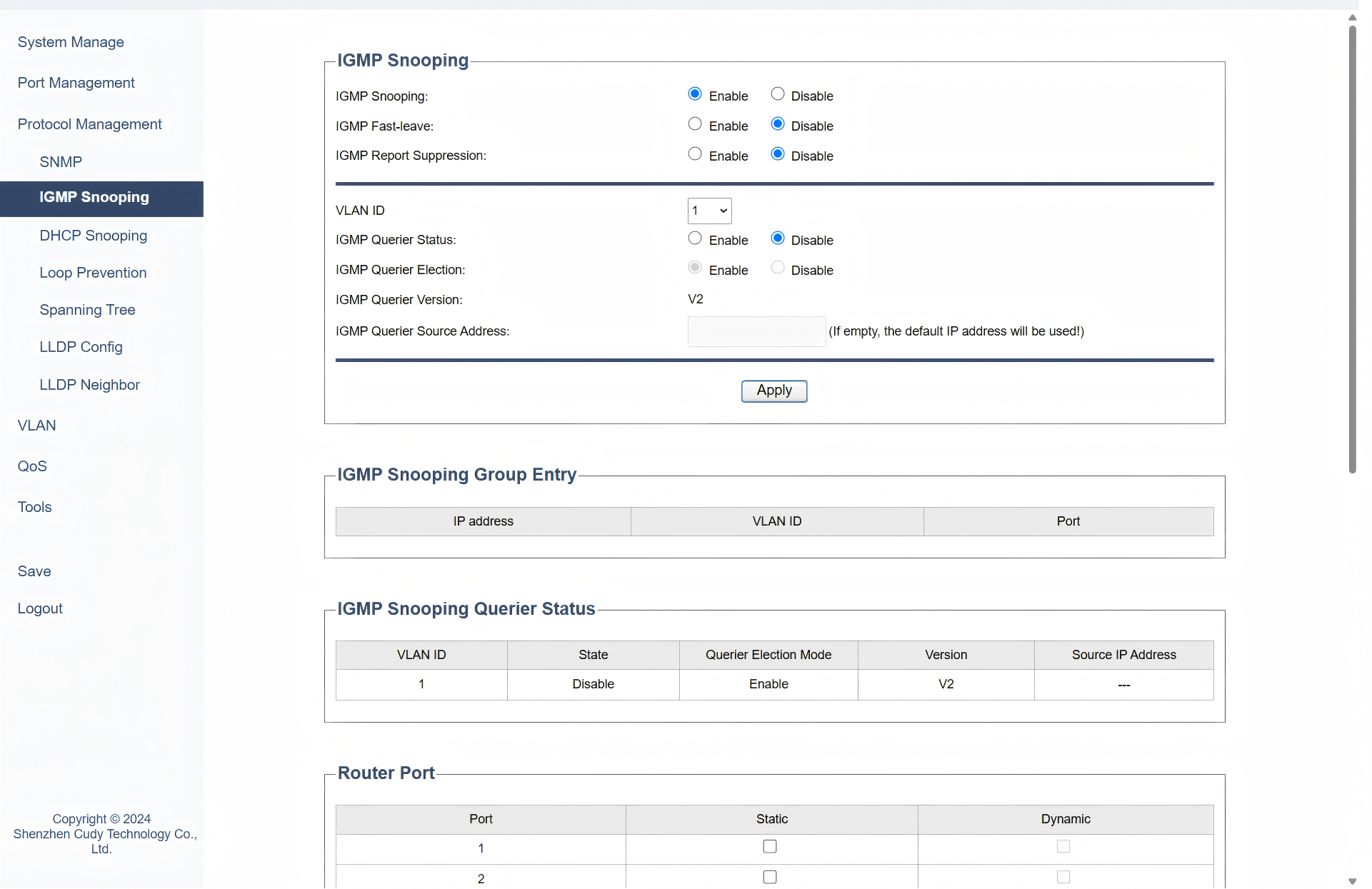
On the Protocol Management >> IGMP Snooping page, you can configure to monitor IGMP messages between hosts and routers, which help to optimize multicast traffic by ensuring that multicast packets are only forwarded to ports where interested receivers are present. Please follow the steps:
1) Configure the following parameters according to your needs. Click Apply.
- IGMP Snooping: Select to Enable or Disable IGMP Snooping globally.
- IGMP Fast-leave: Select to Enable or Disable IGMP Fast-leave, which is a feature that allows a switch to immediately stop forwarding multicast traffic to a port when a host leaves the multicast group, improving network efficiency.
- IGMP Report Suppression: Select to Enable or Disable IGMP Report Suppression. If it is enabled, the first Report Message from the listener will forward to the router ports while the subsequent Report Message will be suppressed to reduce the IGMP packets.
- VLAN ID: Select a VLAN ID from the pull-down list. It is a unique identifier assigned to a virtual local area network (VLAN) that helps in segmenting and managing network traffic.
- IGMP Querier Status: Select to Enable or Disable IGMP Querier Status of a device that sends IGMP queries to hosts to determine which hosts are part of a multicast group.
- IGMP Querier Election: Select to Enable or Disable IGMP Querier Election, a process by which a network elects a single device to act as the IGMP querier, ensuring that only one device sends queries and receives reports.
- IGMP Querier Version: Displays the version of the IGMP protocol used by the querier, which can affect the compatibility and features available.
- IGMP Querier Source Address: Enter the IP address of the device acting as the IGMP querier, which is used to identify the querier in the network. lf left empty, the default lP address will be used!
2) In the table below to view the current IGMP snooping group information, querier status, and router port status.
- IP Address: Displays the IP address of the multicast group.
- VLAN ID: Displays the VLAN ID of the multicast group. All port members of a multicast group should be included in the same VLAN.
-
Port: Displays the forwarding port list of the multicast group.
-
VLAN ID: Displays the ID of VLAN on which the IGMP querier is operating.
- State: Displays the current operational state of the IGMP querier.
- Querier Election Mode: Displays the state of Querier Election Mode.
- Version: Displays the version of the IGMP protocol used by the querier.
-
Source IP Address: Displays the IP address of the device acting as the IGMP querier.
-
Port: Lists the port number on the switch.
- Static: Indicates that the port configuration is manually set and does not change automatically.
- Dynamic: Indicates that the port configuration can change automatically based on network conditions or protocols.
DHCP Snooping
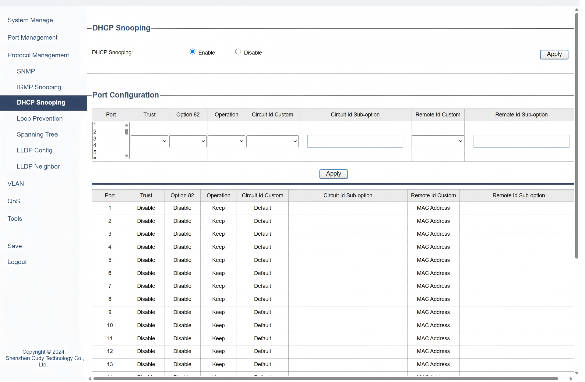
On the Protocol Management >> DHCP Snooping page, you can configure it to prevent unauthorized DHCP servers from assigning IP addresses to devices on the network and help protect against IP address spoofing and ensures that only legitimate DHCP servers can operate. Please follow the steps:
1) Select to Enable or Disable DHCP Snooping, and click Apply.
2) Configure the following parameters, and click Apply. The table below will display the updates and settings.
- Port: Select the specific port to configure DHCP Snooping.
- Trust: Select to Enable or Disable it. Enable Trust will allow DHCP packets to pass through without inspection.
- Option 82: Select to Enable or Disable the inclusion of DHCP Option 82 information, which adds details like the client's physical location to DHCP requests.
- Operation: Select to specify how to handle DHCP Option 82 information: Keep the original, Replace it with new information, or Drop it entirely.
- Circuit ID Custom (Default or User Config): Select to allow customization of the Circuit ID in DHCP Option 82 or not.
- Circuit ID Sub-option: Only when User Config is selected in Circuit ID Custom field can you customize a specific part of the Circuit ID.
- Remote ID Custom (MAC Address, IP Address or User Config): Select how to define the source of the Remote ID in DHCP, whether the MAC address, IP address, or a user-defined value.
- Remote ID Sub-option: Only when User Config is selected in Remote ID Custom field can you customize a specific part of the Remote ID.
Loop Prevention
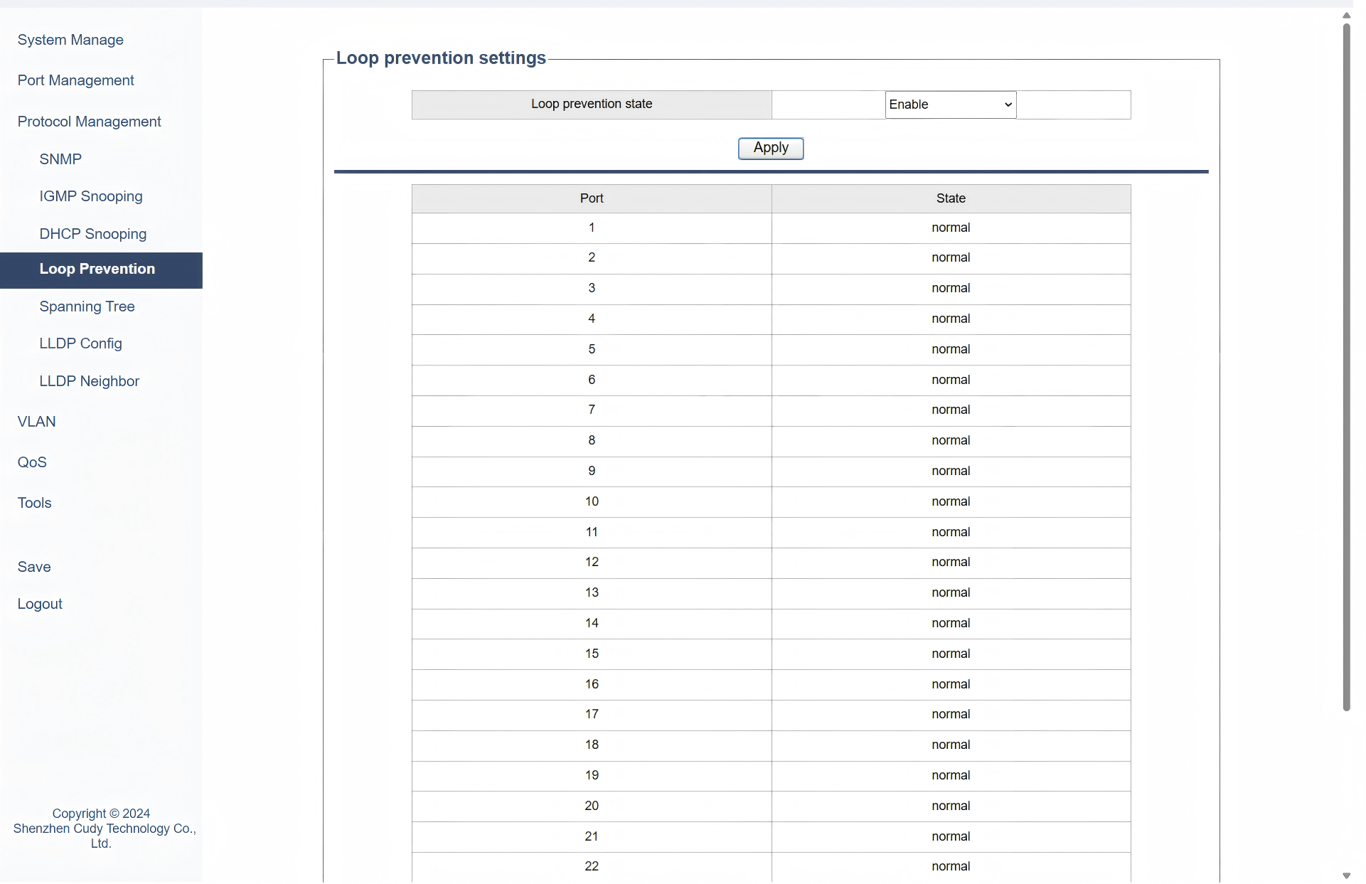
On the Protocol Management >> Loop Prevention page, you can configure it to avoid the creation of loops that can cause broadcast storms and network instability. Please follow the steps:
1) Select to Enable or Disable Loop Prevention State. Enable it to avoid network loops and potential broadcast storms or disable it when necessary in specific controlled environments where loops are managed differently.
2) Click Apply to save and apply the settings or changes.
3) View the table below to ensure the port is in the Normal State, which indicates the port is functioning correctly without any detected loop conditions or issues and normal traffic flow is allowed through the port.
Spanning Tree
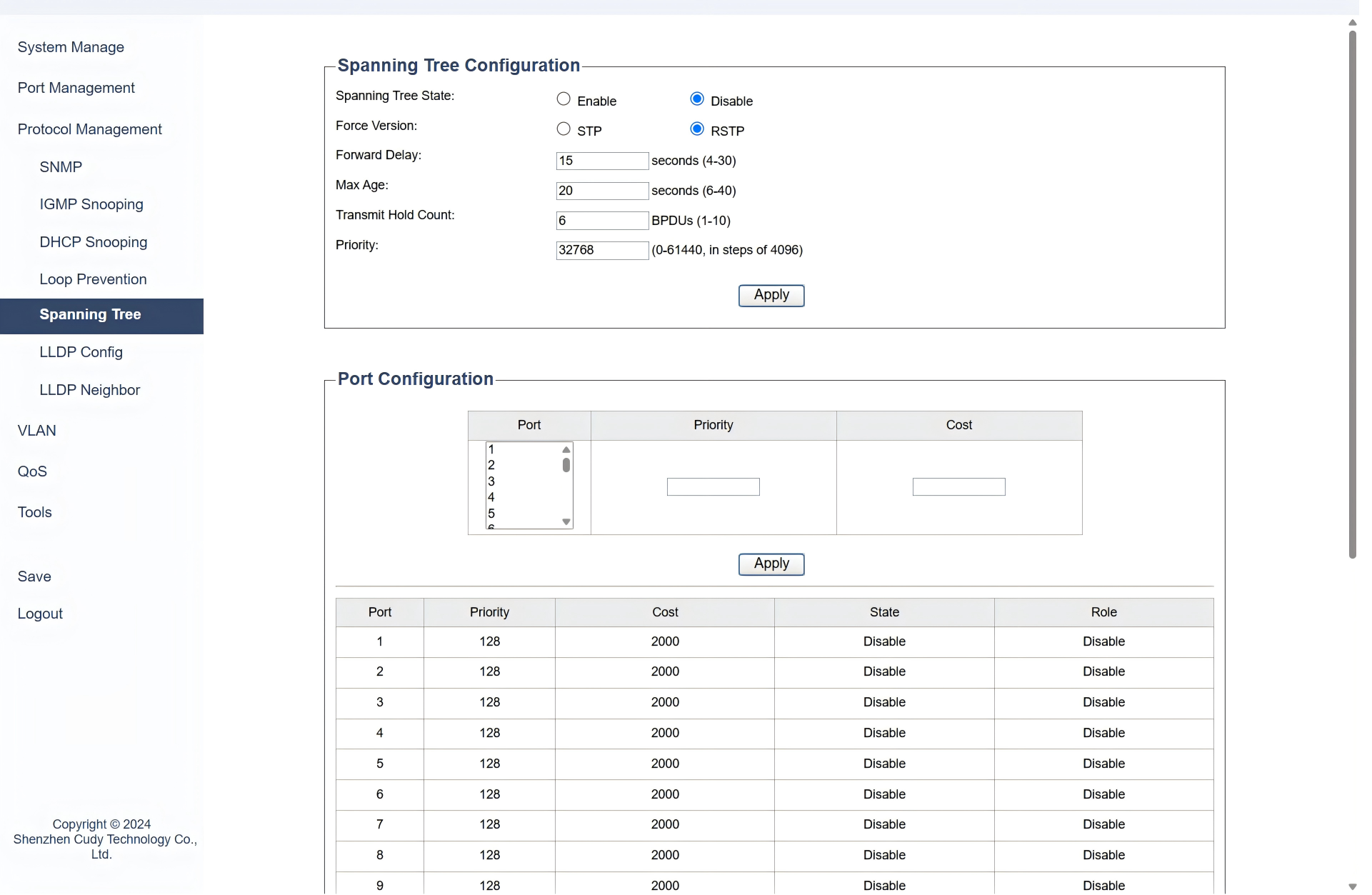
On the Protocol Management >> Spanning Tree page, you can configure STP to prevent loops in a network by ensuring that there is only one active path between any two network devices, which is achieved by creating a loop-free topology using a tree structure. Please follow the steps:
-
Configure the Spanning Tree:
1) Select to Enable or Disable Spanning Tree State.
2) Select a Force Version of STP according to your need. RSTP is better recommended.
- STP: Original protocol for preventing network loops, with slower convergence (30-50 seconds);
- RSTP: Enhanced version of STP with faster convergence (less than 10 seconds).
3) Configure the following parameters according to your need, or just leave it as default.
- Forward Delay: Enter the time interval (between 4 to 30 seconds) that a port spends in the listening and learning states before transitioning to the forwarding state.
- Max Age: Enter the maximum time (between 6 to 40 seconds) that a switch stores a BPDU (Bridge Protocol Data Unit) before discarding it.
- Transmit Hold Count: Enter the number (between 1 to 10) of BPDUs that can be sent before the switch waits for an acknowledgment.
- Priority: Enter a value (between 0 to 61440) that determines the priority of the switch in the STP election process; lower values have higher priority.
4) Click Apply.
-
Configure the Port:
1) Select the Port to be configured.
2) Enter a Priority value (a multiple of 16, between 0 to 240) assigned to the port that influences its role in the STP election process; lower values have higher priority. The value will then display in the table below it.
3) Enter a Cost metric assigned to the port that affects path selection; lower costs are preferred. The value will then display in the table below it.
4) Click Apply.
5) View the table below for the port configurations.
- State: Displays the current operational state of the port.
- Role: Displays the role of the port in the STP topology.
Note
- Configure STP/RSTP of switches first and then connect them together to avoid the broadcast storm.
- Here we only simply enable RSTP on the switches and the corresponding ports. The root switch, root ports, designated ports and blocked ports will be elected automatically. If you need to set a specific switch as the root port, or specify a port to be blocked, please set the priority of the switch and the path cost of the ports according to your needs.
LLDP Config
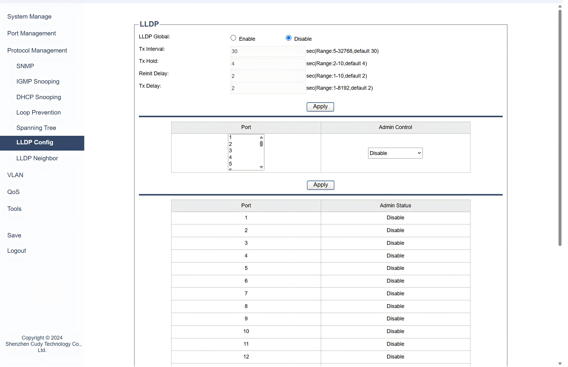
On the Protocol Management >> LLDP Config page, you can configure LLDP (Link Layer Discovery Protocol) to exchange information between adjacent network devices, which helps in discovering device information, such as device type, port details, and VLAN information, which can be useful for network management and troubleshooting. Please follow the steps:
1) Select to Enable or Disable LLDP globally.
2) Configure the following parameters according to your need, or just leave it as default.
- Tx Interval: Enter the time interval (between 5-32768 seconds) between LLDP transmissions.
- Tx Hold: Enter the time (between 2-10 seconds) of LLDP transmissions before considering a neighbor lost.
- Reinit Delay: Enter the delay time (between 1-10 seconds) before reinitializing LLDP after a failure.
- Tx Delay: Enter the delay time (between 1-8192 seconds) before starting LLDP transmissions after initialization.
3) Select the Port to be configured, and select a type of Admin Control for LLDP on this port according to your need.
- Disable: LLDP is completely disabled on the port, preventing both transmission and reception of LLDP packets.
- Tx Only: The port transmits LLDP packets but does not receive them, useful for unidirectional information sharing.
- Rx Only: The port receives LLDP packets but does not transmit them, allowing it to gather information without broadcasting.
- Tx & Rx: The port both transmits and receives LLDP packets, enabling full bidirectional communication for comprehensive network discovery.
4) Click Apply.
LLDP Neighbor
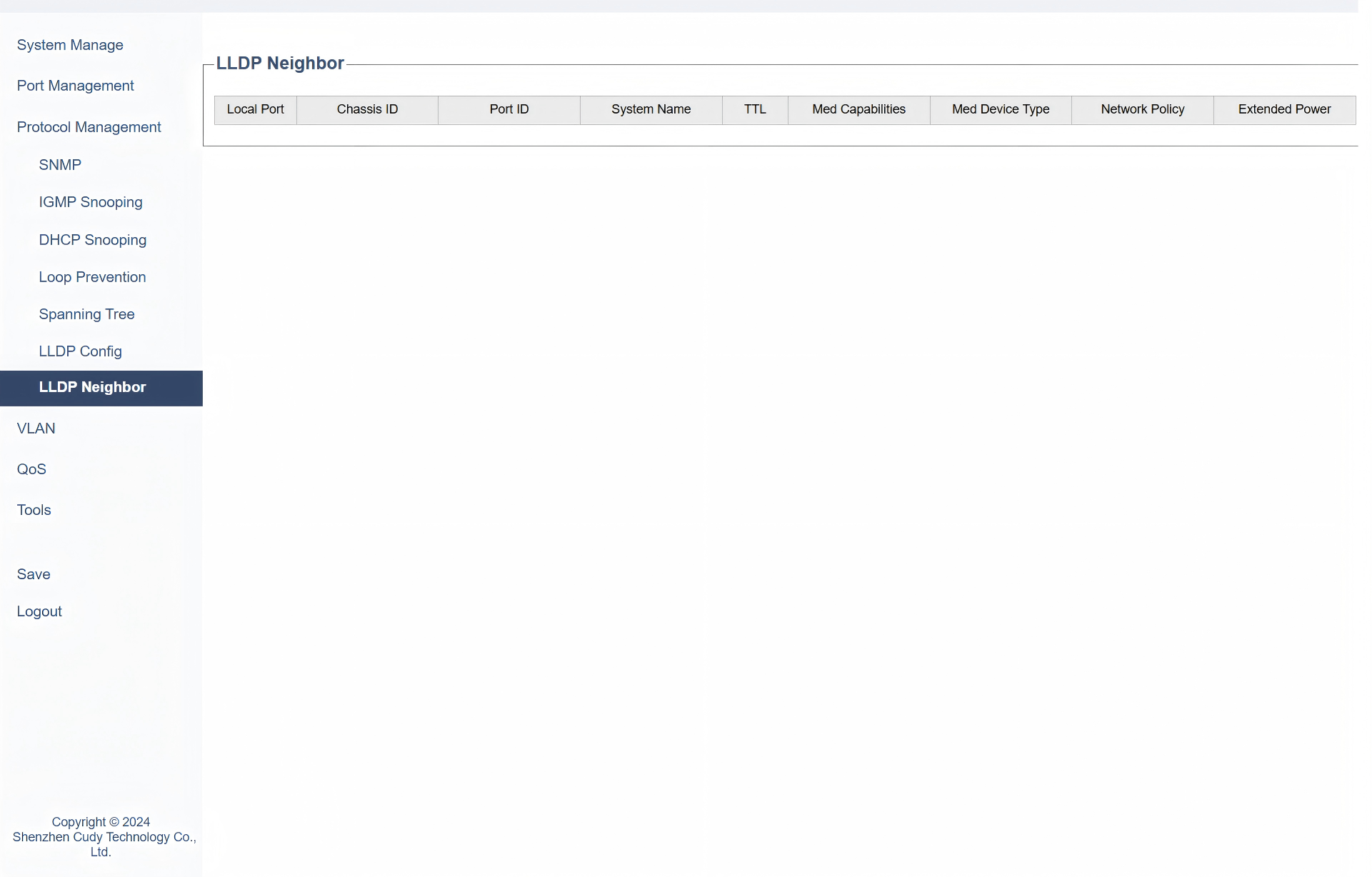
On the Protocol Management >> LLDP Neighbor page, you can view the information about the adjacent devices discovered via LLDP, including:
- Local Port: The port on the local switch where the neighbor is detected.
- Chassis ID: A unique identifier for the neighboring device’s chassis or system.
- Port ID: The identifier of the port on the neighboring device.
- System Name: The name of the neighboring device.
- TTL: Time To Live, indicating how long the LLDP information is valid before it is refreshed.
- Med Capabilities: Media Endpoint Discovery capabilities of the neighboring device.
- Med Device Type: The type of media endpoint device.
- Network Policy: Network policies associated with the neighboring device.
- Extended Power: Information about power consumption or power-related capabilities of the neighboring device.