Input/Output
Status
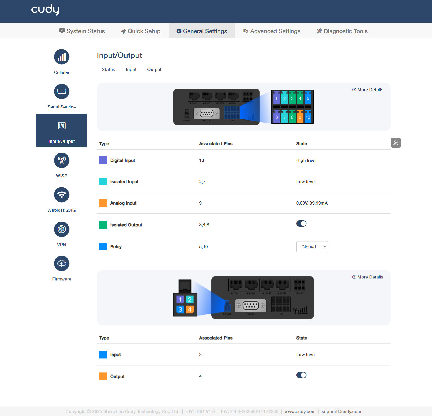
About I/O
- Digital Input (Associated Pin 1/6): Detects high-level signals (e.g., 24V) for equipment status monitoring (limit switches/sensors).
- Isolated Input (Associated Pin 2/7): Reads low-level signals (0V) with galvanic isolation (≥1500V) for safety interlock/emergency stops.
- Analog Input (Associated Pin 9): Supports 0-10V/4-20mA signals for precision measurement (temperature/pressure transmitters).
- Isolated Output (Associated Pin 3/4/8): Transistor outputs (On=0V, Off=high-Z) for driving relays/solenoids (≤0.5A load).
- Relay (Associated Pin 5/10): Electrically isolates control circuits from power circuits (e.g., 5V PLC → 240V motor). Select Closed (NO) when energized (current flows to load) or Open (NC) when de-energized (failsafe/default state).
Note
Use ferrite beads on analog wires to suppress EMI in noisy environments.
About PWR
- Input (Associated Pin 3): Receives external power to activate the device.
- High Level (Typ. 24V±10%): Normal power reception, device operational
- Low Level (<1V): Power loss/undervoltage (check wiring/supply voltage)
- Floating: Open circuit (verify terminal connection integrity)
- Output (Associated Pin 4): Supplies regulated power to connected peripherals.
- On: Actively supplying power to peripherals (e.g., 24V/5V output enabled)
- Off: Output disabled (manual shutdown or protection triggered)
Input
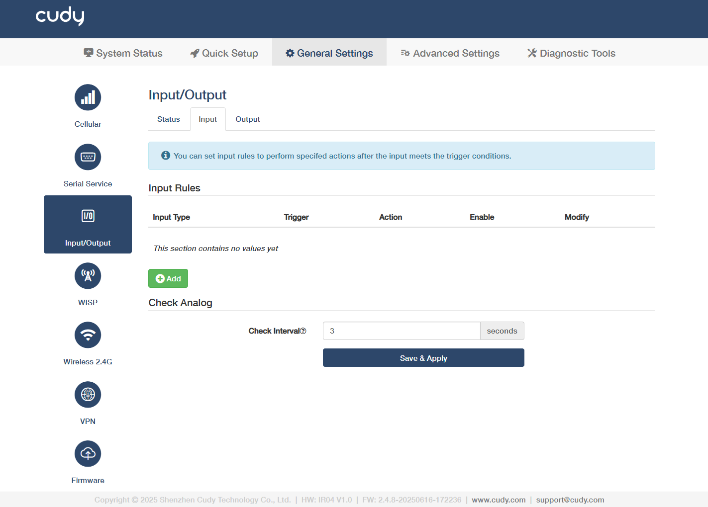
Click Add to configure input rules to perform specified actions after the input meets the trigger conditions.
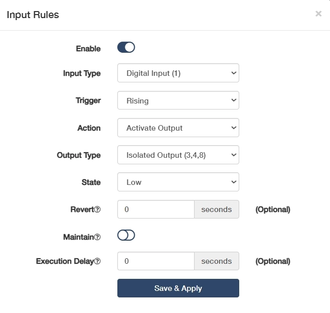
- Click to Enable this entry of input rule.
-
Select an Input Type to define the signal category (e.g., digital/analog/pulse).
- Digital Input(1): Standard binary input for detecting 24V signals.
- Isolated Input(2,7): Galvanically separated input for safety-critical signal.
- Digital Input(Power Socket 3): Power-monitoring input, detecting mains voltage presence via socket status.
- Analog Input(6,9): Reads 0-10V/4-20mA signals for precision measurement.
-
Select a Trigger condition to activate the rule.
-
For Digital/Isolated Input, Rising triggers when signal transitions from low to high, ideal for power-on events; Falling triggers when signal transitions from high to low, used for emergency stop detection; Both responds to any voltage change, perfect for pulse counting or state monitoring.
-
For Analog Input, Inside Range triggers when the signal stays between Min/Max values; Outside Range triggers when the signal exceeds Min/Max thresholds.
-
-
Select Analog Type (for Analog Input) to match your sensor's output signal type.
- Current (mA) is used for 4-20mA/0-20mA industrial sensors (like pressure transmitters) as it’s resistant to signal degradation over long distances;
- Voltage (V) is used for 0-10V/±10V signals (like position sensors) with simpler wiring but shorter effective range due to voltage drop.
- Minimum (V) / Maximum (V) (for Analog Input): Set voltage thresholds to define the valid range for voltage-based triggers.
- Minimum (mA) / Maximum (mA) (for Analog Input): Configure current limits for current-loop device monitoring.
-
Select an Action to execute when the rule is triggered.
- Activate Output: Triggers a designated output port. Then select a target Output Type and current input State, enter a Revert interval to determine auto-reset after trigger ends; enable or disable Maintain to decide lock state until manual reset.
- Send SMS: Send alert messages via cellular module, which requires configured GSM/GPRS parameters. Edit the SMS Text as needed, add the Phone number to send your SMS.
- SIM Switch: Automatically fails over to the selected backup SIM card when primary cellular signal is lost. Recommended to keep it Auto.
- Turn on WiFi: Enables the router's WiFi for wireless client connections.
- Turn off WiFi: Disables WiFi to conserve power or enhance security.
- Reboot: Restart the system to apply configurations or recover from faults.
-
(Optional) Enter the Execution Delay time when will the action be executed after the rule being triggered.
Done! You have successfully configured an Input rule.
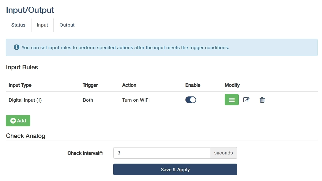
- Modify: Click on
 to edit the entry, or
  to delete the entry.
 - Check Interval: Enter an interval in seconds to check analog input value.
- Save & Apply: Click to save and activate the new settings or changes.
Output
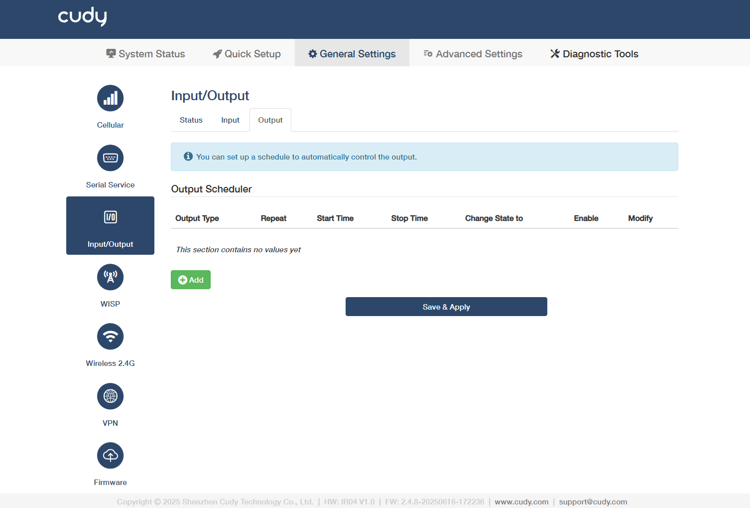
Click Add* to configure output scheduler to perform specified actions after the input meets the trigger conditions.
-
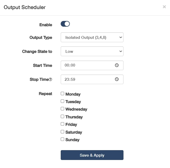
Click to Enable this entry of output scheduler.
-
Select an Output Type and Change State to to define the target output and state.
- Isolated Output (3,4,8): Galvanically separated outputs for sensitive equipment, preventing ground loops in PLC/SCADA systems. Then select Change State to High for activating the optocoupler/solid-state relay to send the preset voltage to the connected device, or Low for cutting off output voltage to create an open circuit.
- Relay (5,10): Electromechanical contacts for switching high-power loads. Then select Change State to Closed for physically connecting the relay’s internal contacts to allow current flow, or Open for breaking the contact to stop current flow.
- Output (Power Socket 4): Direct mains power control for appliances, with built-in overload protection. Then select Change State to High for enabling mains power output, or Low for disconnecting mains power (safety cutoff).
-
Set Start Time for a-new-day shift start, and Stop Time for end-of-day shutdown. And specify Repeatweekdays for cyclical automation of the output schedule.
- Weekdays (Mon-Fri): Ideal for factory equipment schedules (e.g., conveyor activation at 08:00-17:00).
- Weekends (Sat-Sun): Used for non-routine operations (e.g., backup system tests).
- 7-Day Cycle: For 24/7 critical systems (e.g., server room cooling).
Done! You have successfully configured an Output Scheduler.
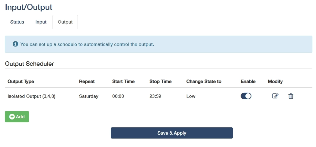
-
Modify: Click on
to edit the entry, or to delete the entry. -
Save & Apply: Click to save and activate the new settings or changes.