General Settings
AP Management
This enables centralized control, configuration, and monitoring of wireless APs (Access Points), including auto-discovery, group policies, and real-time status tracking.
Note
A maximum of 10 APs or 100 clients are allowed in Main Router and AP Controller mode; while a maximum of 200 APs are allowed in AP Controller mode.
AP List
Enables individual configuration and management for the APs, which are in the factory default state and connected in the same subnet with the AP controller.
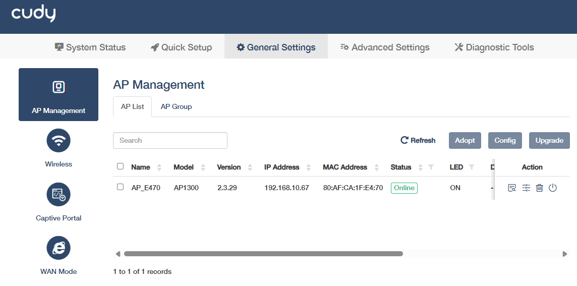
- Name: Displays the AP's name - user-defined identifier for the AP. Edit in Config.
- Model: Displays the AP's hardware model. Auto-detected; used for compatibility checks.
- Version: Displays the AP's firmware version. Use Upgrade to update if outdated.
- IP Address: Displays the AP's static or Dynamic IP address. Configure in Config.
- MAC Address: Displays the AP's physical address. Immutable; useful for filtering/tracking.
- Status: Shows Online/Offline/Adopting. Troubleshoot if Offline.
- LED: Monitors AP status through indicator lights. Turn it OFF in Config when light interference needs to be avoided.
- Description: Optional notes for the AP. Add in Config.
- Channel: Displays the AP's current frequency channel, in the format of XX(2.4G),XX(5G). Adjust in Config.
- Clients: Shows the amount of connected devices. Check in View-Clients for details.
-
Tx/Rx Bytes: Shows data transmitted/received. Monitor bandwidth usage.
-
Action
 : View AP details, including Overview, Radio, Clients and SSID.
 : Configure the settings, including Name, LED Status, and 2.4GHz/5GHz channel, etc.
 : Forget and remove AP from controller but still in the network.
 : Reboot the AP system remotely for fixes/updates.
- Refresh: Update real-time stats.
- Adopt: Authorize unmanaged APs to join controller.
- Upgrade: Install firmware updates.
AP Group
Enables batch configuration for the APs in the same AP group, which can be created and customized.
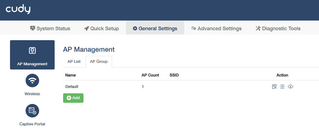
How to create an AP Group?
-
Click
 and create a name for the group. Click Save & Apply.
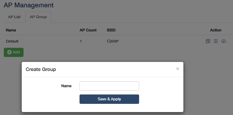
-
Click
and then , select a groupable AP to add it into the group. Click Save & Apply.
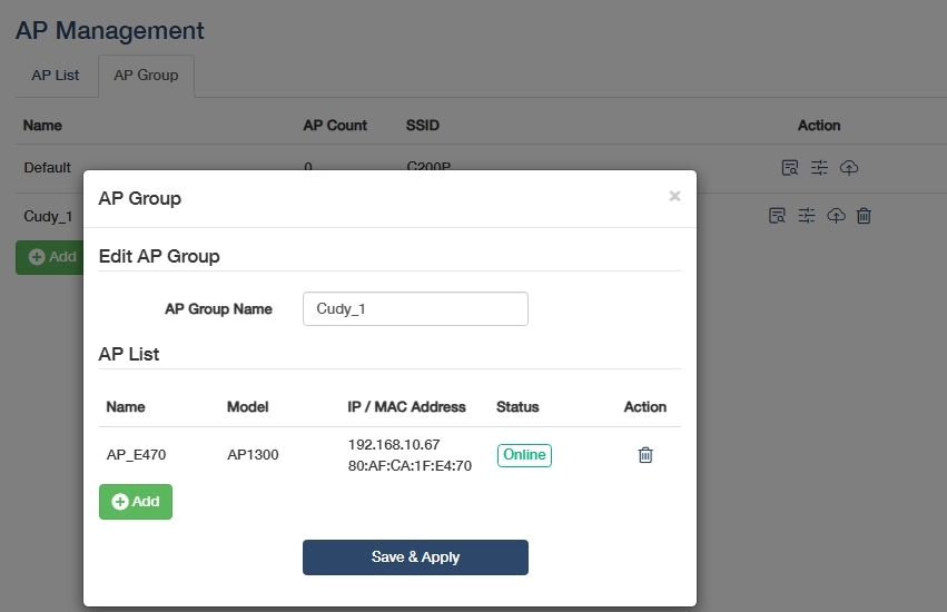
How to manage the APs in the same AP group?
-
: Batch-configure the APs in the same group.
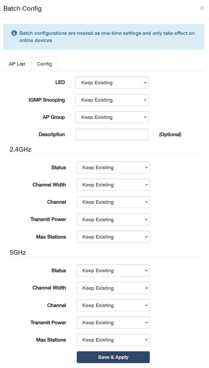
- LED: Keep Existing, or select ON for visibility or OFF for power saving.
- IGMP Snooping: Keep Existing, or select ON to optimize multicast traffic by filtering unnecessary streams to reduce network load.
- AP Group: Keep Existing, or assigns APs to other group.
- Description: Add notes for easy AP Group identification.
- (2.4G/5G) Status: Keep Existing, or select to turn ON or OFF the AP's 2.4G/5G Wi-Fi.
- (2.4G/5G) Channel Width: Keep Existing, or select Auto to adjust bandwidth for optimal speed and interference balance.
- (2.4G/5G) Channel: Keep Existing, or select Auto for automatic channel selection to avoid congestion.
- (2.4G/5G) Transmit Power: Keep Existing, or select Maximum/Medium/Minimum signal strength for coverage control.
- (2.4G/5G) Max Stations: Keep Existing, or select Custom to limit client connections per AP to prevent overload.
-
 : Upgrade the firmwares of the APs in the group.
-
: Forget and remove AP groups from controller but still in the network.
-
: Reboot the AP systems remotely for fixes/updates.
Note
APs in the same AP group will share an identical SSID, while different AP groups should have different SSIDs. Refer to General Settings -> Wireless for more detailed configurations.
Wireless
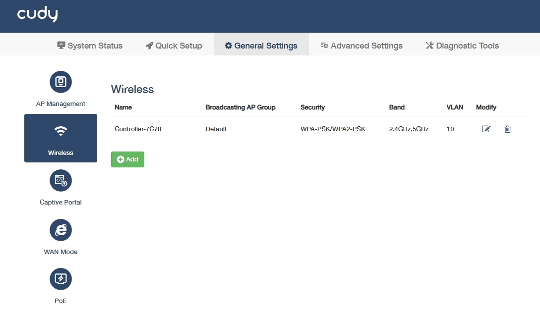
To configure and manage wireless network settings for the controlled APs.
-
Name: Displays the wireless network name (SSID) visible to wireless clients.
Note
APs in the same AP group will share an identical SSID, while different AP groups should have different SSIDs.
-
Broadcasting AP Group: Displays the AP Group of access points sharing this wireless configuration.
- Security: Displays the encryption and authentication methods for network protection.
- Band: Displays the frequency range used for wireless transmission.
- VLAN: Displays this AP group's VLAN ID for traffic segregation. Wireless client data frames are encapsulated with the configured 802.1Q VLAN tag upon egress from the AP's LAN interface.
-
Modify: Click
 to edit the entry or
 to delete the entry.
-
 : Click to add a new entry for an AP group's wireless configuration.
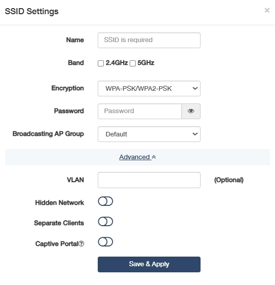
- Name: Modify or customize the wireless network name.
- Band: Enable or disable 2.4GHz/5GHz to specify the frequency range.
- Encryption: Select a security protocol to prevent unauthorized access.
- WPA-PSK: Legacy TKIP encryption, vulnerable to attacks, deprecated.
- WPA2-PSK: AES-based standard, secure but susceptible to brute-force.
- WPA-PSK/WPA2-PSK: Mixed mode for backward compatibility, weakest link dictates security.
- WPA2-PSK/WPA3-SAE: Transitional mode, AES+SAE for future-proofing.
- WPA3-SAE: Quantum-resistant, SAE protocol, ideal for critical infrastructure.
- Password: Set a password for the wireless network.
- Broadcasting AP Group: Select an AP Group for the access points.
- VLAN: (Optional) Assign a VLAN ID (10-4094) to this AP group/SSID to enable traffic segregation. Then ensure the connected switch port is configured as an 802.1Q trunk with the corresponding VLAN allowed.
- Hidden Network: Enable to avoid SSID broadcast and hide the network from casual scans but offers minimal security. Use only with WPA3 for industrial IoT.
- Separate Clients: Enable to isolate connected devices and block their communication, critical for IoT security in shared networks.
- Captive Portal: Enable a login/authentication gateway to control access. It is editable only when General Settings -> Captive Portal is enabled.
Captive Portal
Allows you to design a portal page for network access verification. Customers are directed to view an advertisement or accept set terms before being granted Internet access. In this way, it offers unique marketing opportunities for small businesses to improve brand awareness and deliver marketing messages.
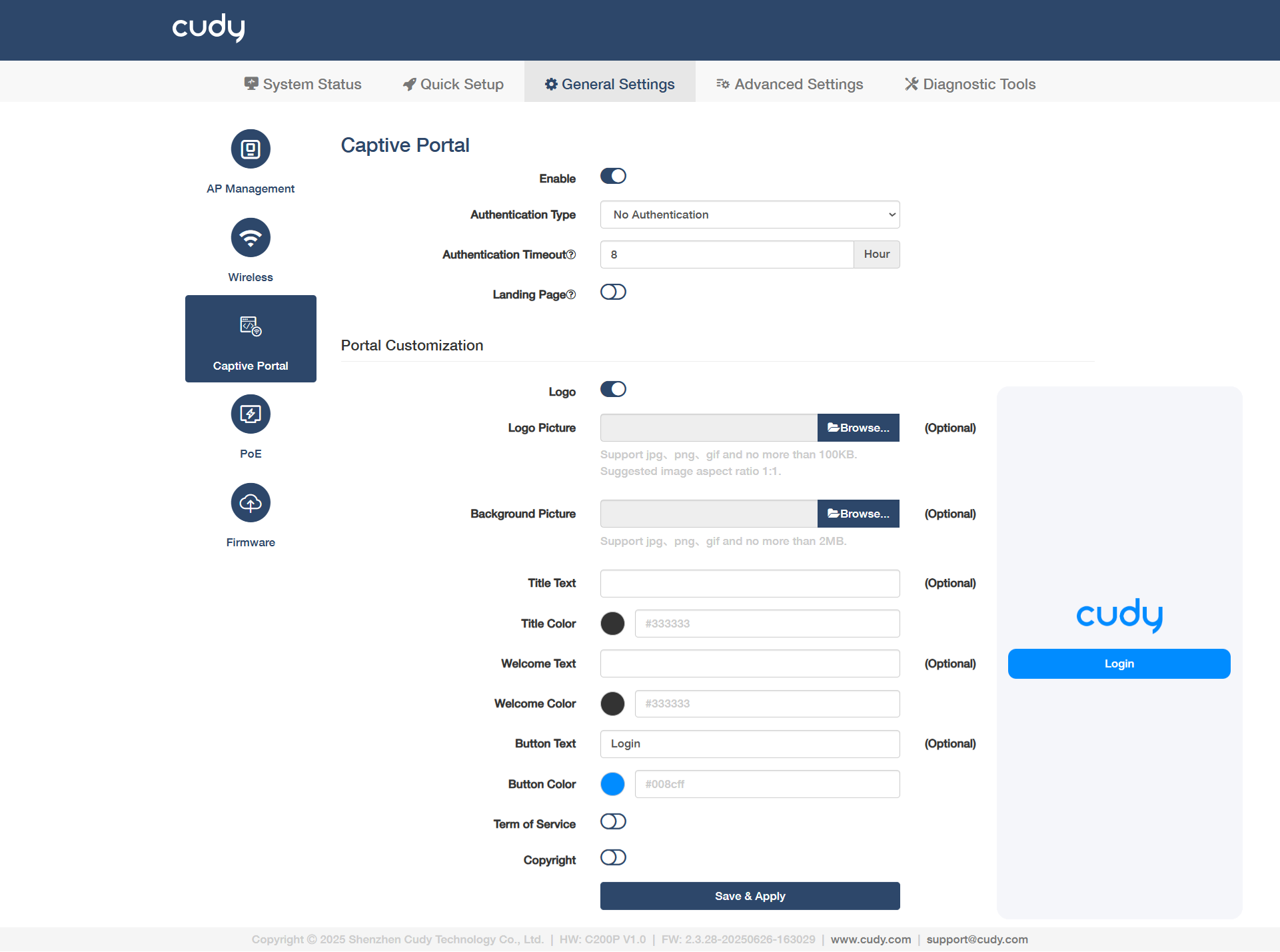
- Enable: Toggle to activate the Captive Portal feature for the APs.
- Authentication Type: Select to define the login method.
- No Authentication: Open network with no login required (e.g., public Wi-Fi).
- Local Password: Uses a pre-shared key (PSK) stored on the AP/controller (e.g., WPA2-Personal for simple private networks). When selected, it is required to set a password.
- External Portal Server: Redirects authentication to an external system.
Continue to configure the below parameters if No Authentication/Local Password is selected as the Authentication Type:
- Authentication Timeout: Sets the maximum time in seconds for users to complete authentication.
- Landing Page: Enable it and enter the URL you would like to redirect the clients/users to see before logging in.
- Portal Customization: Customize the portal's visual design and content.
- Logo: Enable to display a logo on the login page.
- Logo Picture: Click Browse... to locate and upload the logo image file, e.g., company logo.
- Background Picture: Click Browse... to locate and upload a background image for the portal.
- Title Text: Edit the main heading, e.g., "Welcome to Guest Wi-Fi".
- Title Color: Adjust the color of the title text.
- Welcome Text: Customize the secondary greeting message.
- Welcome Color: Change the color of the welcome text.
- Button Text: Modify the login button label.
- Button Color: Set the button's background/text color.
- Term of Service: Enable it and customize legal terms users must accept.
- Copyright: Enable it and set the copyright info at the page footer.
Continue to configure the below parameters if External Portal Server is selected as the Authentication Type:
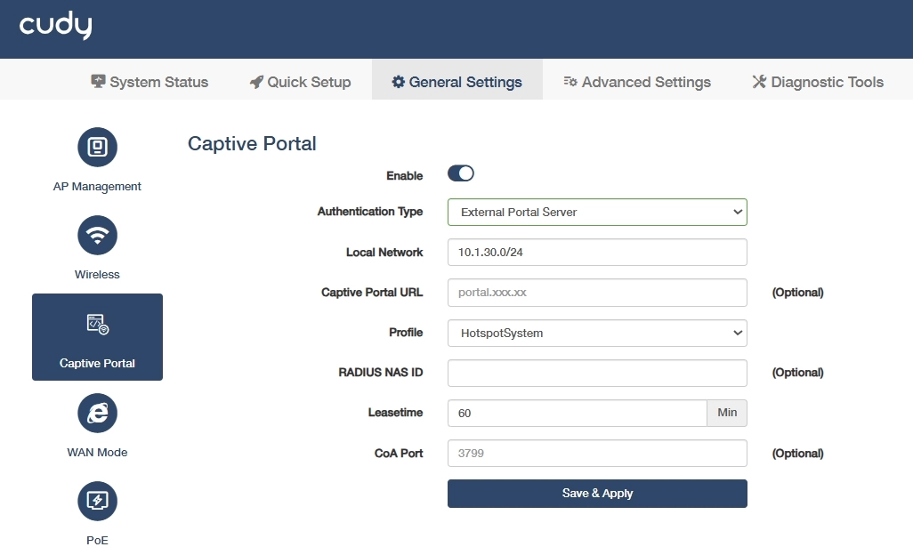
- Authentication Type: Select External Portal Server to delegate authentication to an external system.
- Local Network: Define the VLAN/IP range for unauthenticated clients. Set the field to an unused /24 private subnet that matches the guest VLAN on your switch or firewall; if none exists, keep the default 10.1.30.0/24 and ensure the upstream port carries the corresponding VLAN tag.
- Captive Portal URL: (Optional) Specify the redirect URL for authentication.
-
Profile: Choose a pre-configured portal template or custom profile for branding.
- HotspotSystem: A commercial-grade portal for monetized or branded guest Wi-Fi, configured via cloud dashboard with payment/voucher options.
- Iron Wi-Fi: Social media-focused authentication (e.g., Facebook login), set up by API integration and splash page customization.
- ObiFi: SIM-like secure access for enterprises, configured with data plans and RADIUS/SSO integration.
- VulaCoin: Blockchain-based Wi-Fi with crypto payments, requiring wallet integration and token rules.
- WorldSpot.net: Geo-fenced portals for location-based content, set up via GPS zones and local ads.
- WiFiMAX: Carrier-scale Wi-Fi management (ISPs), deployed with RADIUS and bandwidth throttling.
- Manual: Fully customizable (HTML/CSS), ideal for developers or unique protocols.
-
RADIUS NAS ID: (Optional) For HotspotSystem/lron Wi-Fi/WorldSpot.net/WiFiMAX only. Enter a unique identifier for the AP/controller in RADIUS logs.
- Lease time: Set session duration before re-authentication.
- CoA Port: RADIUS Change of Authorization port (default 3799) for dynamic policy updates.
- UAM Secret: (Optional) For Iron Wi-Fi/WorldSpot.net only. Enter a shared key for secure communication between the portal and authentication server.
- UAM Server: (Optional) For VulaCoin/WiFiMAX only. A dedicated service handling authentication (e.g., payment verification for VulaCoin or RADIUS-coordinated access control for WiFiMAX).
- RADIUS Secret: (Optional) For Iron Wi-Fi/WorldSpot.net only. Enter the password used to encrypt RADIUS protocol exchanges.
WAN Mode
This is only available in Main Router and AP Controller mode.
It defines how the AP controller (working in Main Router and AP Controller mode) connects to the Internet or an external network. Proper setup ensures seamless integration with the main router and ISP requirements. Select an appropriate type of Internet connection and configure the required parameters.
DHCP
Automatically obtains IP address, subnet, and DNS from ISP's DHCP server (plug-and-play).
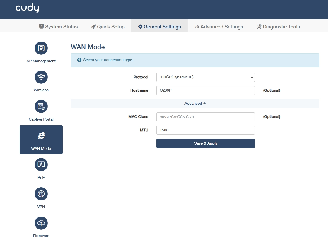
- Hostname: Customize the device's network identifier, used for management and DNS resolution.
- MAC Clone: Spoof a custom MAC address on the WAN interface.
- MTU: Maximum Transmission Unit (bytes) for WAN packets. Keep it default or adjust max packet size to avoid fragmentation.
Click Save & Apply to save and activate the settings or changes.
PPPoE
Requires username/password to authenticate with ISP (common for DSL/cable), encapsulating data in PPP frames.
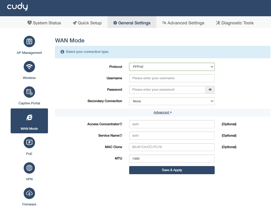
- Username: Enter the ISP-provided login ID for PPPoE authentication.
- Password: Enter the ISP-provided secret key paired with the username to establish a PPPoE connection.
- Secondary Connection: Optional backup Static/DHCP link for failover (if primary fails).
- Access Concentrator: Leave it empty for auto-detection, or manually enter the ISP's PPPoE server name.
- Service Name: Leave it empty for auto-detection, or manually enter the ISP-specific PPPoE service identifier.
- MAC Clone: Spoof a WAN MAC address to match ISP-registered devices.
- MTU: Maximum Transmission Unit (bytes) for WAN packets. Keep it default or adjust max packet size to avoid fragmentation.
Click Save & Apply to save and activate the settings or changes.
Static (Fixed IP)
Manually configure IP, gateway, and DNS (for servers/VoIP needing consistent addressing).
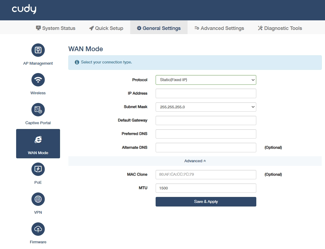
- IP Address: Enter the unique public or private IPv4 address assigned to your AP's WAN interface.
- Subnet Mask: Defines the network segment, e.g., 255.255.255.0 for a /24 range.
- Default Gateway: Enter the AP's IP where traffic exits to the wider network.
- Preferred DNS: Enter a primary DNS server for domain resolution.
- Alternate DNS: (Optional but recommended) Enter a backup DNS server if the primary fails.
- MAC Clone: Spoof a custom MAC address on the WAN interface.
- MTU: Maximum Transmission Unit (bytes) for WAN packets. Keep it default or adjust max packet size to avoid fragmentation.
Click Save & Apply to save and activate the settings or changes.
L2TP / PPTP
VPN tunneling protocol (often paired with IPsec) for secure remote site connections over public networks.
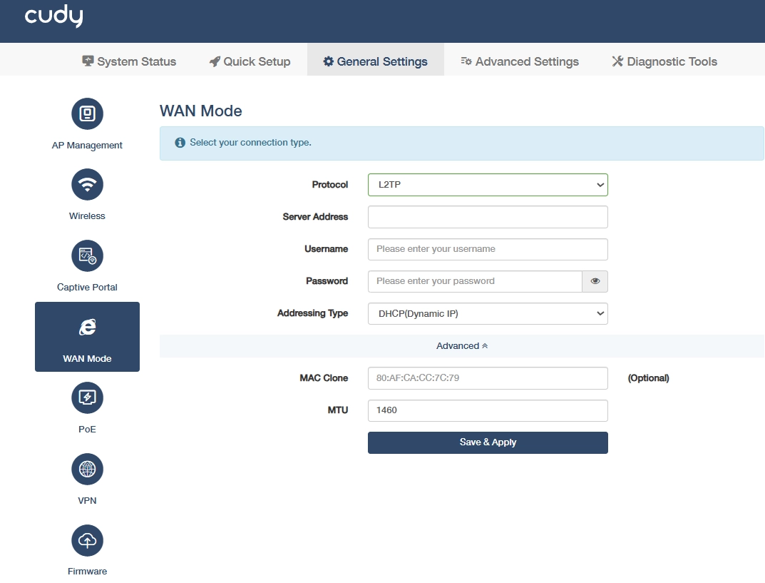
- Server Address: Enter the IP/hostname of your L2TP VPN server.
- Username/Password: Enter the credentials for L2TP authentication (often paired with IPsec pre-shared keys).
- Addressing Type: Choose between Dynamic IP (DHCP-assigned) or Static IP (manual WAN IP for VPN).
- MAC Clone: Override the WAN interface MAC address.
- MTU: Maximum Transmission Unit (bytes) for WAN packets. Keep it default or adjust the packet size to avoid fragmentation.
Click Save & Apply to save and activate the settings or changes.
LAN
The AP controller is preset with a default LAN IP 192.168.10.1, which you can use to log in to its web management page. The LAN IP address together with the Subnet Mask also defines the subnet that the connected devices are on. If the IP address conflicts with another device on your local network or your network requires a specific IP subnet, you can change it.
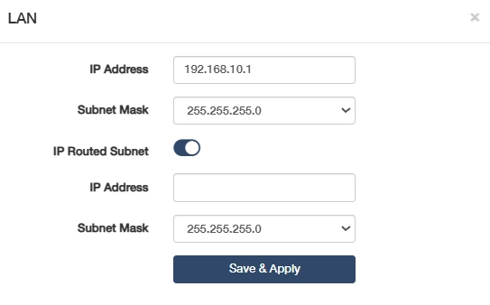
- Enter a new IP Address appropriate to your need.
- Set the Subnet Mask or keep it as default.
- Enable IP Routed Subnet as needed. If it is enabled, you need to enter the IP Address and Subnet Mask as well.
- Click Save & Apply.
Note
- If you have set the Port Forwarding, DMZ or DHCP address reservation, and the new LAN IP address is not in the same subnet with the old one, then you should reconfigure these features.
- If in conflict with the WAN IP address, the LAN IP will automatically change into 10.1.1.1.
PoE
Allows remote control of power delivery to connected access points via Ethernet cables.
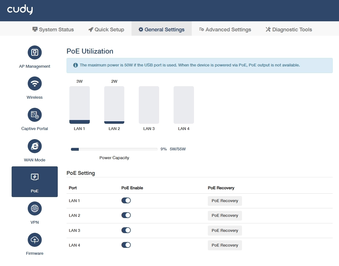
PoE Utilization
- LAN 1/2/3/4: Displays PoE-capable Ethernet ports and their real-time power consumption and allocation status.
- Power Capacity: Displays real-time usage (e.g., 2W/55W, 4%), showing current draw vs. max capacity to monitor load balance and prevent overloads.
Note
When the device is powered via PoE, PoE output is not available. The maximum power is 50W if the USB port is used.
PoE Setting
- Port: Displays the specific LAN 1~4 ports for configuration.
- PoE Enable: Toggle to disable or enable PoE power delivery for the specified port.
- PoE Recovery: Click to restore power to the port after a reboot or fault condition.
VPN
This is only available in Main Router and AP Controller mode.
VPN (Virtual Private Network) helps you access Internet resources remotely, securely, and privately through tunneling technology. When you access the Internet, VPN encrypts your personal information and hides your IP address from the public. For VPN users, it looks like the devices are directly connected. Cudy Router supports 6 types of VPN connections: PPTP, L2TP, OpenVPN, WireGuard, ZeroTier, IPSec (site-to-site). Please choose an appropriate VPN according to your needs and circumstances.
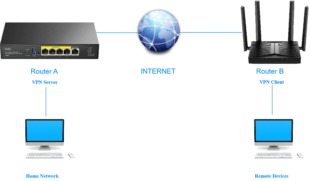
Note
- Here demonstrates with AP controller working in Main Router and AP Controller mode as Router A (VPN server) and the other router as Router B (VPN Client).
- Before you enable VPN server, it is recommended to configure Dynamic DNS service or assign a static IP address for router's WAN port and synchronize your system time with Internet.
PPTP VPN
PPTP VPN is used to create a PPTP VPN connection for remote devices to access your home network. Fast connection/disconnection and simple configuration satisfy the needs for users who is apt to frequently switch VPN environments. Please follow the steps below to set up a PPTP VPN connection.
STEP 1. Configure the PPTP Server on Router A:
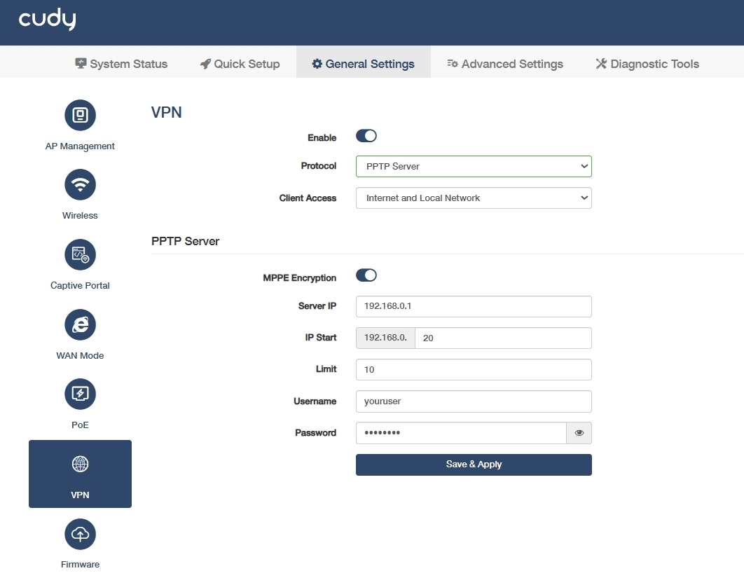
- Log into the AP controller's management web page Cudyac.net or 192.168.10.1.
- Go to General Settings -> VPN. Toggle to enable VPN, and select PPTP Server as Protocol.
- Select an appropriate type of Client Access.
- Internet and Local Network: Allows simultaneous access to both public internet and private LAN resources through the VPN tunnel.
- Internet Only: Routes all traffic through the VPN, masking the client's real IP but blocking local LAN access.
- Local Network Only: Restricts access solely to private network resources, leaving internet traffic to bypass the VPN.
- Configure the PPTP Server.
- MPPE Encryption: Enable to encrypt the data transmitted via PPTP VPN, thus improve the communication security.
- Server IP/IP Start/Limit: Set to assign IP address for the VPN Clients.
- Username/Password: Set for the VPN client to access the VPN Server.
- Click Save & Apply.
STEP 2. Configure PPTP Client on Router B:
.webp)
- Log into the Router B's management web page http://cudy.net or 192.168.10.1.
- Go to General Settings -> VPN. Enable VPN, and select PPTP Client as Protocol.
- Select Allow all devices or Ban all devices as Default Rule.
- Allow all devices: Permits all VPN-connected devices to access the local network by default. Convenient but less secure.
- Ban all devices: Blocks all devices by default, requiring manual exceptions. More secure but needs configuration.
- Enable Site-to-Site to allow communication between VPN server and Clients.
- Select an appropriate VPN Policy.
- Disable: VPN Policy is disabled. No restriction.
- VPN kill switch: Internet access will be disconnected upon VPN disconnection. It is highly recommended for users who transmit data all through VPN. Preferred (and optionally Alternate) DNS is required.
- Domain: Select and configure to allow specified domain(s) to transmit data through VPN or not. DNS and Domain are required.
- Remote Subnet: Select and configure to allow devices with the specified subnet to transmit data through VPN. IP address and Subnet mask are required.
- Configure the PPTP Client:
- Server Address/Username/Password: Enter the parameters provided by the PPTP Server.
- Encryption: Enable to ensure the data security for the PPTP clients.
- Click Save & Apply.
L2TP VPN
L2TP VPN Server is used to create a L2TP VPN connection for remote devices to access your home network. Compared with PPTP, L2TP supports multi-tunnel with authentication between two endpoints, thus users can set up different tunnels with various service quality. Please follow the steps below to set up a L2TP VPN connection.
STEP 1. Configure the L2TP Server on Router A:
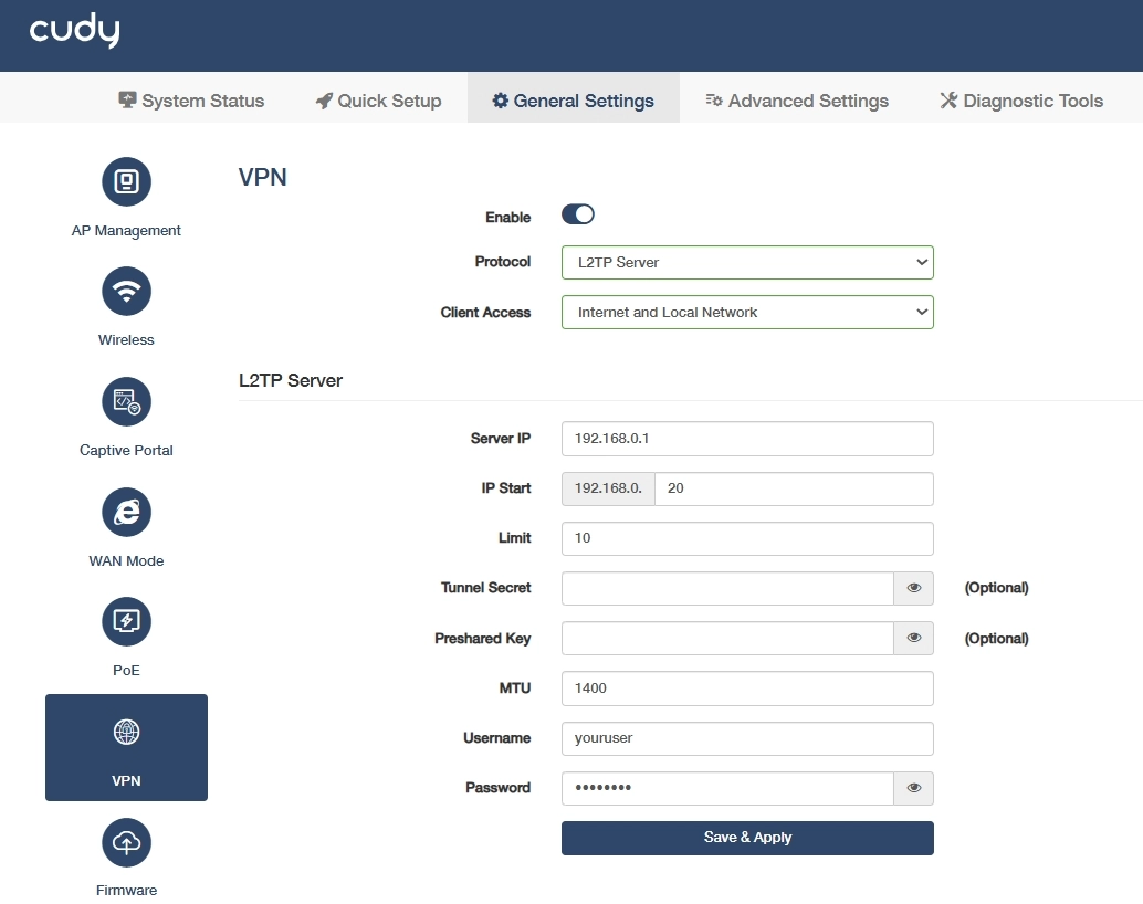
- Log into the AP controller's management web page Cudyac.net or 192.168.10.1.
- Go to General Settings -> VPN. Enable VPN, and select L2TP Server as Protocol.
- Select an appropriate type of Client Access.
- Internet and Local Network: Allows simultaneous access to both public internet and private LAN resources through the VPN tunnel.
- Internet Only: Routes all traffic through the VPN, masking the client's real IP but blocking local LAN access.
- Local Network Only: Restricts access solely to private network resources, leaving internet traffic to bypass the VPN.
- Configure the L2TP Server.
- Server IP/IP Start/Limit: Set to assign IP address for the VPN Clients.
- Tunnel Secret (Optional): To set a L2TP VPN encryption as needed.
- Pre-shared Key (Optional): To set a IPSec encryption as needed.
- MTU: Maximum Transmission Unit is 1400 by default. You may change it if necessary.
- Username/Password: Set to authenticate the VPN clients to access the VPN Server.
- Click Save & Apply.
STEP 2. Configure L2TP Client on Router B:
.webp)
- Log into the Router B's management web page https://cudy.net (or 192.168.10.1).
- Go to General Settings -> VPN. Enable VPN, and select L2TP Client as Protocol.
- Select Allow all devices or Ban all devices as Default Rule.
- Allow all devices: Permits all VPN-connected devices to access the local network by default. Convenient but less secure.
- Ban all devices: Blocks all devices by default, requiring manual exceptions. More secure but needs configuration.
- Enable Site-to-Site to allow communication between VPN server and Clients.
- Select an appropriate VPN Policy.
- Disable: VPN Policy is disabled. No restriction.
- VPN kill switch: Internet access will be disconnected upon VPN disconnection. It is highly recommended for users who transmit data all through VPN. Preferred (and optionally Alternate) DNS is required.
- Domain: Select and configure to allow specified domain(s) to transmit data through VPN or not. DNS and Domain are required.
- Remote Subnet: Select and configure to allow devices with the specified subnet to transmit data through VPN. IP address and Subnet mask are required.
- Configure the L2TP Client:
- Server Address/Username/Password: Enter the parameters provided by the PPTP Server.
- Local Hostname: Customize or keep it as default.
- Tunnel Secret/Pre-shared Key: Enter the encryption if the L2TP Server has set it.
- MTU: Maximum Transmission Unit is 1400 by default, you may change it if necessary.
- Use custom tunnel IP: Enable and enter it if the L2TP Server provides a tunnel IP bound with the account.
- Click Save & Apply.
OpenVPN
OpenVPN Server is used to create an OpenVPN connection for remote devices to access your home network.
OpenVPN server requires a public IP. You can confirm whether the router has a public IP on the router management page System Status -> WAN -> More details -> Status. If the public IP displayed is consistent with the IP address of the router's WAN port, it means that the router has a public IP. Please follow the steps below to set up an OpenVPN connection.
STEP 1. Configure the OpenVPN Server on Router A:
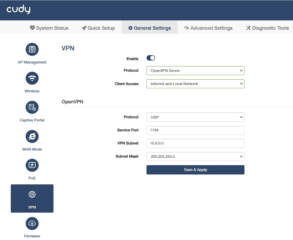
- Log into the AP controller's management web page Cudyac.net or 192.168.10.1.
- Go to General Settings -> VPN. Enable VPN, and select OpenVPN Server as Protocol.
- Select an appropriate type of Client Access.
- Internet and Local Network: Allows simultaneous access to both public internet and private LAN resources through the VPN tunnel.
- Internet Only: Routes all traffic through the VPN, masking the client's real IP but blocking local LAN access.
- Local Network Only: Restricts access solely to private network resources, leaving internet traffic to bypass the VPN.
- Configure the OpenVPN Server.
- OpenVPN Protocol: Select UDP or TCP as desired.
- Service Port: 1194 by default, keep it or change it as needed.
- VPN Subnet: Set up a VPN subnet segment.
- Subnet Mask: Select or customize as needed.
- Click Save & Apply.
- Click EXPORT to export the configuration file, for the OpenVPN Client to upload.
STEP 2. Configure OpenVPN Client on Router B:
.webp)
- Log into the Router B's management web page https://cudy.net (or 192.168.10.1).
- Go to General Settings -> VPN. Enable VPN, and select OpenVPN Client as Protocol.
- Select Allow all devices or Ban all devices as Default Rule.
- Allow all devices: Permits all VPN-connected devices to access the local network by default. Convenient but less secure.
- Ban all devices: Blocks all devices by default, requiring manual exceptions. More secure but needs configuration.
- Enable Site-to-Site to allow communication between VPN server and Clients.
- Select an appropriate VPN Policy.
- Disable: VPN Policy is disabled. No restriction.
- VPN kill switch: Internet access will be disconnected upon VPN disconnection. It is highly recommended for users who transmit data all through VPN. Preferred (and optionally Alternate) DNS is required.
- Domain: Select and configure to allow specified domain(s) to transmit data through VPN or not. DNS and Domain are required.
- Remote Subnet: Select and configure to allow devices with the specified subnet to transmit data through VPN. IP address and Subnet mask are required.
- Click Browse... to locate the Configuration file (client.ovpn) you exported previously from the OpenVPN Server. The uploaded configuration file will be automatically read and the Server IP will be displayed.
- Click Save & Apply.
WireGuard VPN
WireGuard VPN Server is used to create a Wire Guard VPN connection for remote devices to access your home network.
WireGuard VPN server requires a public IP. You can confirm whether the router has a public IP on the router management page System Status -> WAN -> More details -> Status. If the public IP displayed is consistent with the IP address of the router's WAN port, it means that the router has a public IP. Please follow the steps below to set up a WireGuard VPN connection.
STEP 1. Configure the WireGuard Server on Router A:
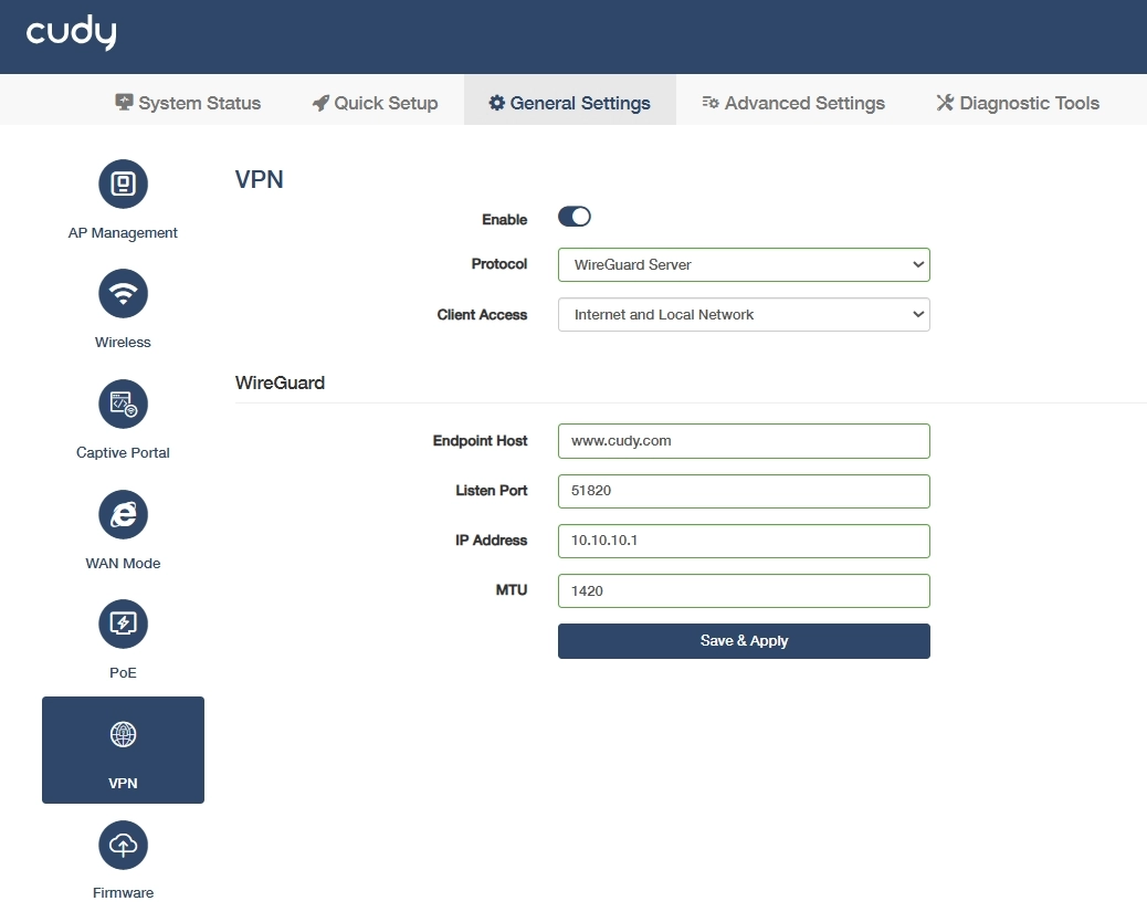
- Log into the AP controller's management web page Cudyac.net or 192.168.10.1.
- Go to General Settings -> VPN. Enable VPN, and select WireGuard Server as Protocol.
- Select an appropriate type of Client Access.
- Internet and Local Network: Allows simultaneous access to both public internet and private LAN resources through the VPN tunnel.
- Internet Only: Routes all traffic through the VPN, masking the client's real IP but blocking local LAN access.
- Local Network Only: Restricts access solely to private network resources, leaving internet traffic to bypass the VPN.
-
Configure the WireGuard Server:
- Endpoint Host: Public domain/IP for VPN clients to connect. Configure with either your public IP or a DNS domain, and ensure port forwarding/NAT rules on your router direct traffic to the AP controller's local IP.
- Listen Port: Designated port for VPN service to receive connections. Keep default unless port conflict/ISP blocking occurs.
- IP Address: Private LAN IP of the VPN server. Keep default unless subnet changes or IP conflicts arise.
- MTU: Packet size limit to optimize tunnel performance. 1420 by default. Keep default unless experiencing packet loss then reduce slightly.
-
Click Save & Apply.
- Then you will be required to configure the Client parameters. Click Edit Item.

- Click Add to add entries. Enter the required parameters and then click Save.
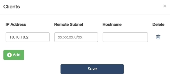
- IP Address: Assign a static LAN IP to the client (e.g., 192.168.1.101) for stable access. Do ensure it's outside DHCP range.
- Remote Subnet: Specify the client's local subnet (e.g., 10.8.0.0/24) to enable cross-network access. Used for site-to-site VPNs.
- Hostname: Optional identifier (e.g., Branch-Office-1) for easier management.
- Click to export the configuration file, which is to be uploaded on the client for connection.

STEP 2. Configure WireGuard Client on Router B:
.webp)
- Log into the Router B's management web page https://cudy.net (or 192.168.10.1).
- Go to General Settings -> VPN. Enable VPN, and select WireGuard Client as Protocol.
- Select Allow all devices or Ban all devices as Default Rule.
- Enable Site-to-Site to allow communication between VPN server and Clients.
-
Select an appropriate VPN Policy.
- Disable: VPN Policy is disabled. No restriction.
- VPN kill switch: Internet access will be disconnected upon VPN disconnection. It is highly recommended for users who transmit data all through VPN. Preferred (and optionally Alternate) DNS is required.
- Domain: Select and configure to allow specified domain(s) to transmit data through VPN or not. DNS and Domain are required.
- Remote Subnet: Select and configure to allow devices with the specified subnet to transmit data through VPN. IP address and Subnet mask are required.
-
Click Browse... to locate the Configuration file (wg-client-x.conf) you exported previously from the WireGuard Server. The uploaded configuration file will be automatically read and such parameters as below will be displayed.
- Confirm the parameters and then click Save & Apply.
ZeroTier VPN
Zerotier is a third-party cloud platform for VPN connections. It can establish a VPN connection without any public IP address node to achieve secure and remote access. It is free for use with less than 50 nodes. It is simple and convenient to set up. Please follow the steps below to set up a ZeroTier VPN connection.
STEP 1. Register for a ZeroTier Account and Obtain a Network ID.
- Visit Zerotier website http://my.zerotier.com/, sign up for an account and log in.
.webp)
- Click Network - > Create A Network.
.webp)
- Zerotier will create a new network and assign a NETWORK ID for you. Then click on the assigned NETWORK ID, and its setting page will display.
.webp)
-
Set Access Control to be Public for later convenient settings, and note down the Network ID.
.webp)
Note
Private Access Control requires authorization for the terminal or router to access the network, which is more secure but inconvenient. While Public Access Control allows for a direct the network access with authentication rather than authorization. You may choose either one accordingly.
STEP 2. Configure ZeroTier Master on Router A.
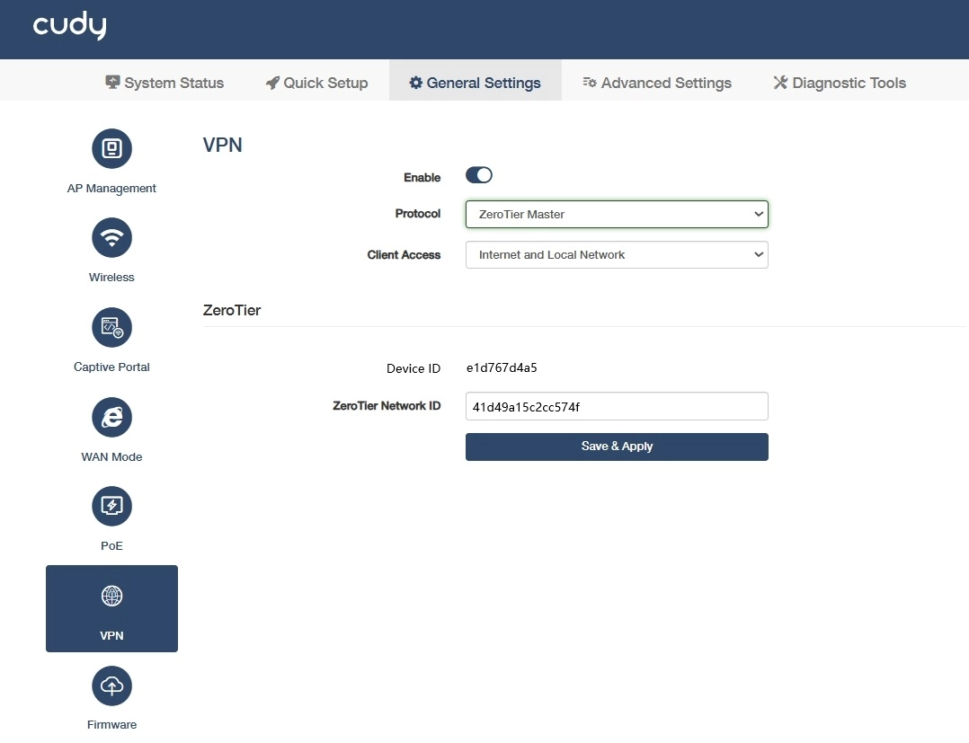
- Log into the AP controller's management web page Cudyac.net or 192.168.10.1.
- Go to General Settings -> VPN. Enable VPN, and select ZeroTier Master as Protocol.
- Select an appropriate type of Client Access.
- Internet and Local Network: Allows simultaneous access to both public internet and private LAN resources through the VPN tunnel.
- Internet Only: Routes all traffic through the VPN, masking the client's real IP but blocking local LAN access.
- Local Network Only: Restricts access solely to private network resources, leaving internet traffic to bypass the VPN.
- Enter the ZeroTier Network ID noted down previously.
- Click Save & Apply. Then it will display the Device ID.
- Back to the ZeroTier web page, you will see One device has joined this network.
.webp)
STEP 3. Join ZeroTier Network on your device.
- Download and Install ZeroTier Software from https://www.zerotier.com/download/.
.webp)
- Click the ZeroTier icon and then Join New Network..., enter the Network ID and click Join.
.webp)
- Back to the ZeroTier web page, you will see this new device and its Managed IP.
.webp)
STEP 4. Configure the Static Route.
Go to Settings -> Advanced on the ZeroTier web page. Under Add Routes, enter Router A's LAN IP segment 192.168.10.0/24 in Destination field and its Managed IP in Via field, and then click Submit.
.webp)
Now your client devices can directly access the AP controller's management web page via 192.168.10.1 as well as the server via its IP address.
IPSec (site-to-site) VPN
It is a secure tunneling protocol used to connect two different networks, typically a corporate network and a remote branch office network, over the Internet. It allows multiple users at the remote site to access resources on the main office network as if they were directly connected to it. Please follow the steps below to set up an IPSec (site-to-site) VPN connection.
STEP 1. Get both Routers in the Headquarter and Branch Office ready.
- Make sure both Routers are connected to the Internet, but two network can not be in the same LAN segment. For example, if the headquarter is in the LAN segment 192.168.10.0/24, then the branches should be in a different LAN segment, say, 192.168.20.0/24.
- Check and note down the WAN and LAN IP addresses of the Headquarter Router and Branch Office Router on their management Status page. WAN IP of the headquarters router is the remote gateway of the branch offices, and its LAN IP is the remote subnet of the branch offices; and vice versa.
STEP 2: Configure the IPSec VPN on the Router in the Headquarter.
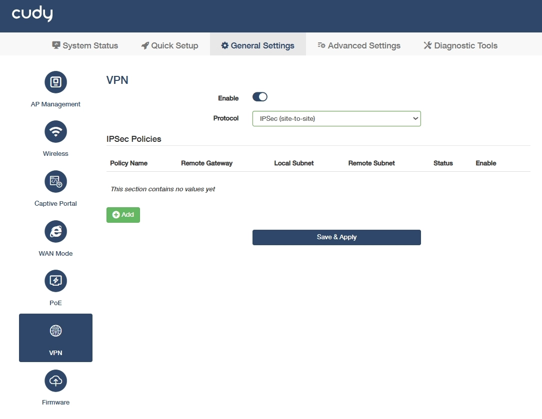
- Log into the AP controller's management web page Cudyac.net or 192.168.10.1.
- Go to General Settings -> VPN. Enable VPN, and select IPSec (site-to-site) as Protocol.
-
Click Add to add IPSec Policies.
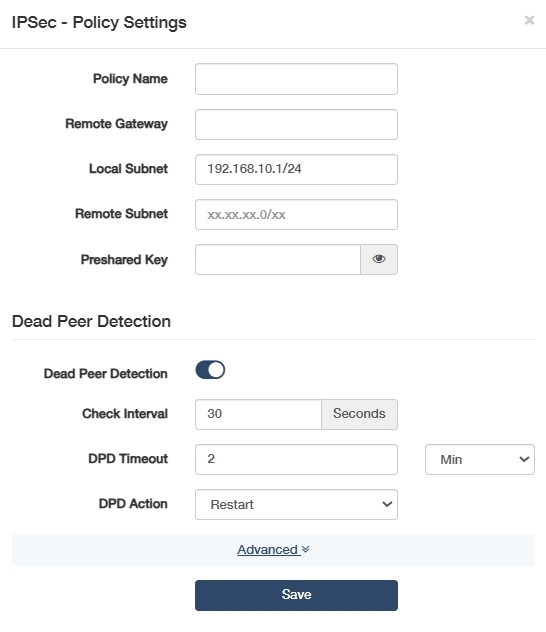
- Policy Name: Name the policy as desired.
- Remote Gateway: Enter the WAN IP of the Router in branch office.
- Local Subnet: Auto-filled the LAN segment of the local router.
- Remote Subnet: Enter the LAN segment of the Router in branch office.
- Pre-shared key: Set an encryption key as desired.
- Dead Peer Detection: Enable to detect whether the peer end is alive or not.
- Check Interval: Keep 30 seconds as default or change as needed.
- DPD Timeout: Set when to perform PDP checking again. Keep 2 Minutes as default or change it as needed.
- DPD Action: Decide what to do after DPD detection failure, Restart, Hold or Clear. It is recommended to keep Restart as default.
-
Click Save & Apply.
STEP 3: Configure the IPSec VPN on the Router in the Branch Office.
- Log into the Router B's management web page https://cudy.net (or 192.168.10.1).
- Go to General Settings -> VPN. Enable VPN, and select IPSec (site-to-site) as Protocol.
-
Click Add to add IPSec Policies.
- Policy Name: Name the policy as desired.
- Remote Gateway: Enter the WAN IP of the Router in the Headquarter.
- Local Subnet: Auto-filled the LAN segment of the local router.
- Remote Subnet: Enter the LAN segment of the Router in the Headquarter.
- Pre-shared key: Enter the encryption key set on the headquarter Router.
- Dead Peer Detection: Set all the settings, including Dead Peer Detection, Check Interval, DPD Timeout, DPD Action, the same as the headquarter Router.
-
Click Save & Apply.
Then, you can go confirm the connection between Headquarter Router and Branch Router.
Note
- If one of the routers does not have a public IP address, for instance the Branch Router, but the Headquarter Router has a public IP address, you can:
- Set Branch Router in the Initiator Mode and change the Headquarter Router from Initiator Mode to Responder Mode.
- Change the remote gateway on the Headquarter Router to be 0.0.0.0.
Firmware
The latest firmware will be released at the Cudy official website www.cudy.com, and you can download it from www.cudy.com/download. Please choose an appropriate update method and follow the instructions.
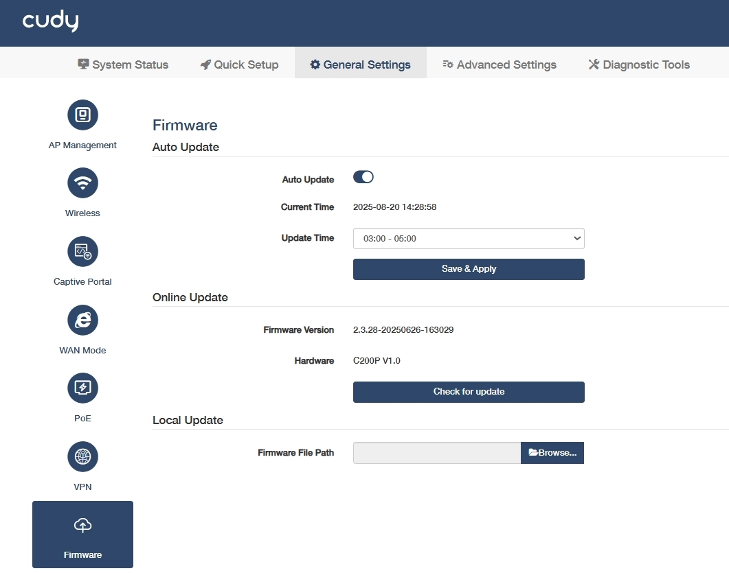
Auto Update
It allows the AP controller to automatically update firmware to the latest version at the specified time.
- Enable Auto Update.
- Specify the Update Time
- Click Save & Apply.
Note
- Backup your AP controller’s configurations before firmware update. Do NOT turn off the AP controller during the firmware update.
Online Update
- If there is a new firmware available for the AP controller, a prompt will appear upon your login to the AP controller web management page. Click Update Now and then Update to upgrade the firmware to the latest version.
- If you miss the prompt, please go to General Settings -> Firmware to check for update. If there is one, click Update and wait a few minutes for the update and reboot to complete.
Local Update
Click Browse... to locate and upload the latest firmware file you’ve downloaded from www.cudy.com. Wait a few minutes for the update and reboot to complete.
Note
- If you fail to update the firmware for the AP controller, please contact our technical support.